Content

tagged: mechatronics

tekton » maker's mark

my favourite bit of tekton is of course what nobody sees, or for that matter should see. this is the view from behind, and while yes, it’s the makers mark, what gets me is the rainbow cable against soft yet rectilinear aluminium. something quite pure about it.

diary | 15 jul 2015 | tagged: dfuse · tekton · mechatronics

tekton » on

it’s on. much gazing.

diary | 10 jul 2015 | tagged: dfuse · tekton · embedded · mechatronics

tekton » on-site assembly

in wood st. galleries. inevitable delays. machine yet to be proven. hours ticking. and so it starts.

diary | 08 jul 2015 | tagged: dfuse · tekton · mechatronics

tekton » mounted

finally, two uprights and the two slide assemblies installed. i am about to spend a lot of time up that ladder.

diary | 08 jul 2015 | tagged: dfuse · tekton · mechatronics

tekton » moving

arduino loops to the microsecond to give smooth motion weren’t the only performance-critical bit of code required. the animation sequence wasn’t playing far too slowly - nowhere near the 60fps the animations were authored for, and now we can see it moving, it was clear it needed to be that fast and smooth to play with your perception as you looked on. updating the oled display and addressing the led pixels was taking too long. i knew you could drive this kind of oled crazy-fast as i’d written my own library from scratch for the mixer hardware, and i knew there was a lower-level way of driving the led strips. so: abandoned updating the oled for the time being, and advanced the controller python code to construct a bytearray per strip rather than set each led individually… and voila! naked-eye illusion. code. tho’, somewhat by definition, the video doesn’t quite capture that (tho’ watch the leds as the bar accelerates up…/).

slms-tobyspark-jun2015-2-dsc_0537

what the above skips over is that if an arduino is now going to sit by the stepper and drive it, the main raspberry pi controller now needs to control the arduino, not the stepper drive’s pulse pins. and so, perhaps inevitably, the custom board i made to extend the pi gets a hack to disconnect two direct control lines and rewire them to the pi’s hardware serial pins. at least the pcb design was good, it’s just that the spec changed!

slms-tobyspark-jun2015-9-dsc_0504

to get this working, the arduino just interpreted the last byte received as a 0-255 value and scaled this up to the step range, around 20,000. that was pretty coarse and certainly less than the precision of the float value supplied in the animation sequence, and so while the machine was in transit i developed a protocol to pack an integer that could represent that kind of number into a series of bytes, keeping things as efficient as possible.

in python, on the controller: from a single byte, coarse and with no messaging capability –

arduinoserial.write(chr(int(float(items[meta_vpos_index])*255)))

which the receiving arduino handles like so…

to three bytes each with two bit command type and six bit payload –

#command 01 = sequence run vpos start
vpos_steps = int(meta[2]*drive_max_steps
arduinoserial.write(chr(0x40 + ((vpos_steps >> 12) & 0x3f)) + chr((vpos_steps >> 6) & 0x3f) + chr(vpos_steps & 0x3f))

which the arduino handles like so…

oh, did i mention there’s two of everything? the model is actually two floor-ceiling bars each with the rails of slide bar, carriage running on them, and led bar cantilevered from the carriage. being way over schedule and needing to ship the model to the gallery in the us, here is the excellent david meckin helping to wire up led bar #2.

slms-tobyspark-jun2015-b-6-dsc_0538

diary | 15 jun 2015 | tagged: dfuse · tekton · embedded · mechatronics

tekton » debug

of course, things are never straightforward and the particular nightmare of this project starts: motion control. every single aspect has problems. start the analysis, isolate issues…

diary | 14 jun 2015 | tagged: dfuse · tekton · embedded · mechatronics

tekton » stepper pulses

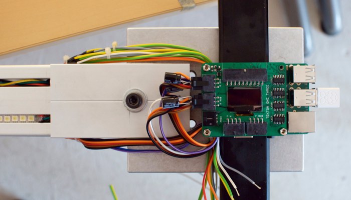
in the midst of those debug wires was a logic analyser that hooks up to a desktop app. best thing ever – thanks again to ninja friend Arron Smith. using the logic probe to examine the control signals, i stripped down the control script to create a constant turn and the result is not good. stepper pulses, top: looks even. stepper pulses, middle: hell no. that’s just a little later in the same sample.

no wonder the motor doesn’t have smooth motion, with the shuddering action making horrible noises and vibrations through the structure. realisation one is that it’s not possible to get the timing precision to get near the pulse frequency to drive the motor at a decent speed, and realisation two is that the timing accuracy is just not there. running this machine from a python script on a raspberry pi with it’s stock linux installation was an experiment, and this is where “let’s try the future” fell down. simply, it’s not a realtime environment. however, a bare bones sketch on an arduino, flipping a digital out between delaymicroseconds() of 5 and up did work beautifully. somehow a middle-ground had to be reached.

the first stage of that was to simulate the 60fps commands of the driving animation while being a stand-alone program. a sin calculation also takes ~120µs on an arduino, considerably longer than the minimum pulse time of around 5-10µs. the beautiful step signal shown bottom is the output of calculating sin(time) every 1/60s, and for every loop in-between, calculating a linear interpolation between the last two sin points, comparing that with the current position, and issuing a step and/or direction change if needed.

later, in the down-time while shipping and the gallery install, i’d spent time working through options to drive the motor better. the machine would run smoothly – purr, even – if i drove it with something known-smooth like a sine wave, but whenever i switched from this a problem appeared. the intention had always been to add some kind of inertial smoothing to the control, so that whatever input the controller took would translate into something that was mechanically viable for the machine. accelerating the led bar puts torque on the linear bearing, and the weight of the whole assembly will simply stall a stepper motor pulsed from still to a constant turn. the answer should be to employ a physical model in the code, which with a little research the accelstepper library effectively does. you can command a step position, and it will take the motor there within a defined envelope of speed and acceleration. every stepper project should use this… except it turns out the maths is too computationally expensive to achieve anything close to stepping fast enough for this project on an 8mhz arduino.

problem was, any other strategy i tried in my own stepper driving code proved insufficient – i had high hopes for a simple median filter. this may have been partly due to the other side of driving the stepper smoothly: the microsecond consistency of pulse timings (as discovered originally, trying to drive direct from the pi). i suspect the serial read of commanded step position from the pi was interfering with this and/or disrupting the exact regularity between received commands that the linear interpolation relied upon.

in hindsight, two things stand out. one is that the raspberry pi is incredibly fast and powerful compared to the arduino, so running such a library fast enough would present no issue, if it ran a realtime operating system akin to the arduino. this required more linux-fu than i had headspace for at the time, but is surely the correct way to go. the other is a little more embarrassing, in that research since has shown the stepper driver – the hardware box that takes the logic level step pulses and makes it so – has an optional smoothing filter that is configurable by software. i never got to this, as mentally the driver was sold as not needing software configuration, the very point being it was pre-tuned for this series of motors, and physically, the interface cable was bespoke and i didn’t buy it. just perhaps breaking that mental mould to make up that cable could have saved me nights worth of grief.

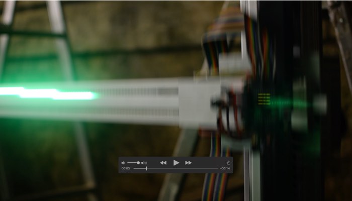
to cut back to sitting in front of the machine with the opening in hours not days, anything that wasn’t that sinusoidal self-driving arduino sketch was causing horrible, horrible sounds (something like a resonant frequency in the half-coupling and splined shaft that slotted into the pulley), and so running sinusoidal was what it was going to be.

and to underline just how crazy the whole motor episode was, simply adding a debug line to send the current position of the motor to the serial console when the belt mid-point marker passes the sensor caused mechanical vibrations that made you want to turn the whole thing off. that’s how sensitive the pulse timings are. throughout, it has been the worst case of observing changing the observed.

diary | 14 jun 2015 | tagged: dfuse · tekton · embedded · mechatronics

tekton » let there be light

LED baton mounted on the vertical slide mounted on the floor-ceiling bar, power supplies installed and wired up, first pass software to run the LED strips… let there be light!

to this point, everything has been to plan and as per researched data sheets. the motors do not prove that way, in any way. mechanically mating them to the pulley end-unit proves to be fraught with issues; likewise for their control.

the particular motor chosen has a shaft that matches the diameter of the bore in the pulley, this i had checked. what i had overlooked, is that unique to this particular motor in the range, the shaft length is much less than the others. so short, that engaging into the pulley is an issue. this requires making a motor mating plate as thin as possible, and some horrible work arounds with offset grub screws, taps and holes where they shouldn’t be, and access holes where they shouldn’t be to be able to tighten the result up. eventually it was done, but it was a bruising night.

having got a mechanical fit of motor to frame and pulley, then onto control. a quick implementation in the python script running the controller, and the vertical position is being read from the text file and translated into stepper pulses to sync the mechanical position. code

so… it’s alive! it works…

slms-tobyspark-jun2015-10-dsc_0499

…but actually it doesn’t. the control isn’t giving smooth operation. it hurts just thinking about the jittery movement and how the cantilevered led bar amplifies that.

diary | 11 jun 2015 | tagged: dfuse · tekton · embedded · mechatronics

tekton » sharp

carriage blocks machined, pcb assembled, parts mounted and LED bars have LED strips fitted and on their way to being wired. damn fiddly, not without it’s trials and certainly time consuming, but looking damn sharp.

fitting the ‘dotstar’ LED strips in particular is both wonderful and frustrating. such a nice fit when fitted, but all sorts of trouble getting in and out, an action liberally aided by silicone lubricant. lots of silicone lubricant. but many gotchas: the rubber sheath stretches as you pull the assembly through, so woe betide you if you need to adjust afterwards or pull out again (which, this being both prototype and first assembly, you’ll end up doing a few times); the dotstars are not continuous strips and you either need to de-solder the appropriate joint of the 60/m low-density strips which sold as 5m rolls but are actually factory soldered 0.5m sections, or completely remove the copious silicone and whatnot of the 1m sections of 144/m high-density strips and solder together. just doing that on the bench could be unreliable, and when sheathed and pulled into the groove… yeah.

diary | 09 jun 2015 | tagged: dfuse · tekton · embedded · mechatronics

tekton » machining

blocks of metal, calipers, drill presses… haven’t done this since mechanical engineering at uni in the nineties.

top photo is me verifying the modifications required for the carriage to fit the baton, the belt bar, and the controller. 11 holes from m3 to m6, some with recessed heads, some tapped.

i spent a long time figuring out what was best to run the led bar up and down. roller wheels on a solid bar came out best, as roller wheels are fast and being at the corners good for torque, and if what they’re running on is incompressible then the carriage should hold square. after asking some specific questions about the various item linear bearing parts to their staff, got a duff answer and what came out the box had ball bearing races. this part was chosen as being aesthetically the neatest, so there’s still good in having them, but there’s more friction than i’d like, and ball races have turned out to be fragile. if there was to be a tekton one three mkii, this is something i’d change.

slms-tobyspark-openingnight

slms-tobyspark-openingnight

diary | 27 may 2015 | tagged: dfuse · tekton · mechatronics